- Press coverage for the Cambridge iGEM team
- Biology at Cambridge
- Growth in liverworts of the Marchantiales is promoted by epiphytic methylobacteria.
- Genetic changes accompanying the domestication of Pea
- Hack an Air Freshener into an Remote Camera Trigger [DIY]
- Planon releases credit card-sized scanner for receipts
- Players control real microorgansims in 'biotic video games'
- CompuLab introduces its smallest, most energy efficient mini-PC to date
- Disposable microfluidic devices created using regular wax paper
- Mussels inspire self-healing sticky gel
- Pentel Airpen Mini now Compatible with Android Devices
- Built your own private network on the Go with Planex latest 3G Wireless Router
- PFU Fujitsu introduced the ultimate document scanner, the N1800
- Hydrogel used to create precise new biochemical sensor
- 80 Free and Awesome Photoshop Brushes
- Giant Knitted Squid
- Nitrogen fixation by marine cyanobacteria.
- Peptide signalling in the rhizobium-legume symbiosis.
- Auxin conjugates: their role for plant development and in the evolution of land plants.
- Illustrated anatomy of Gamera and foes
- Pickle Toothpaste
- Edible Giant Toasted Leafcutter Ants
- Flypaper Clock Eats Flies, Uses Their Bodies for Energy
- New E. chromi video
- Positions at Microsoft Research, Cambridge UK
- iGEM2011 recruitment
- Dynamics in the mixed microbial concourse.
- Making classic frequency counters into Nixie clocks
- The 4x4x4 LED Cube Using an Arduino
- Researchers develop genuine 3D camera
- Microbial Cell Factories: Engineering the cell surface display of cohesins for assembly of cellulosome-inspired enzyme complexes on Lactococcus lactis
- Presidential Commission reports on Synthetic Biology
- Cambridge presentation 2010
- iGEM2010 Jamboree
- Improved BioBrick components for bioluminescence
- Cambridge team at the iGEM2010 Jamboree
- University of Cambridge team wins iGEM synthetic biology competition
- Reversal of an epigenetic switch governing cell chaining in Bacillus subtilis by protein instability.
- App Magnets – upgrade your fridge with some app-etising icons
- Hackintosh In A Cardboard Box
- This Lung-On-A-Chip
- Pickle Adhesive Bandages
- USB Mix Tape
- Monster illustrations from Ultraman sonosheet book
- 15 Cool Stickers for your iPhone
- Bacteria are able to extend psuedo-legs and walk upright
- Japanese flower has the largest known genome
- Gibson Assembly Song
- DIYbio articles in Nature
- Gibson Assembly Song
- In Living Color: Bacterial Pigments as an Untapped Resource in the Classroom and Beyond
- Lego Shaped Ice Cube Tray
- Bacterial physiology: Bacillus takes the temperature
- Microfluidic approaches for systems and synthetic biology.
- GreenPhylDB v2.0: comparative and functional genomics in plants.
- The roots of a new green revolution.
- The Kno: A giant double-screen tablet to replace giant textbooks
- NVIDIA Fermi-Class Quadro GPUs
- Homemade laser microscope reveals water's murky secrets
- Verbatim launches Clip-It USB drive
- Synthetic Biology Faculty position
- SynBio2010 course in Synthetic Biology at Cambridge
- Synthetic Biology worth $4.5B by 2015
- Naked Scientist interview
- Royal Society: Future Technologies
- 2nd-generation GM traits
- NYT article about iGEM2009
- Synthetic Biology at the Wellcome Trust
- Giant Plant Cells
- Glass microbiology
- Endnote X3
- LEGO-sized hole punch
- Glowing Toyama Squid USB Memory Stick
- Green Pins
- Bacterial rainbow
- Synthetic operon for violacein production
- Cambridge team wins Grand Prize for iGEM2009
- The scatalog: E. chromi, pigment and poo
- Grand Prize for Cambridge iGEM2009 team
- Cambridge presentation at the iGEM2009 Jamboree
- Wellcome Trust iGEM2010 studentships
- Cambridge iGEM2009 team
- Synthetic Biology Project
- The iGEM Project
- RS Interface SynBio issue
- steam-powered dragon tin toy
- Magcloud: On Demand Magazine Printing
- RAE Synthetic Biology Report 2009
- Arduino Mega
- Phytocomp - new computing tools for plant science
- Computational Biology at Microsoft Research in Cambridge
- Open source hardware 2008
- www.synbio.org.uk news feeds
- Cambridge Network News
- iGEM 2008: Novice Bioengineers
- Plastic Logic e-Reader
- High Speed Photography using the Arduino
- Visitor's Guide to Cambridge
- Graduate Studies at Cambridge
- Emergence: a foundation for Synthetic Biology in Europe
Making classic frequency counters into Nixie clocks
Making classic frequency counters into Nixie clocks: "One of our favorite longstanding projects-- which we dropped a hint about some time ago --is converting old HP Nixie-tube counters into happily glowing Nixie clocks. Here's how we do it.
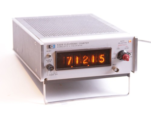
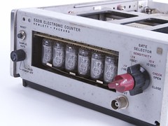
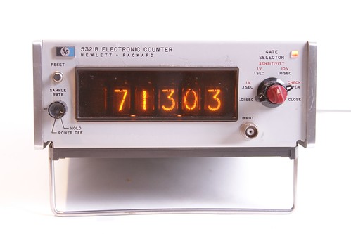
We've converted a few different types, but our favorite clocks come from HP 5321B and 5221B electronic counters. These frequency counters were produced from about 1968-1970, in that brief window of time where the control electronics had transitioned from discrete-transistor logic to integrated circuits, but Nixie tubes were still the preferred display technology. (By 1971, HP's catalog was full of counters with high-tech light-emitting diode displays.)
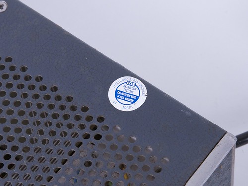
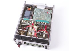
You can often pick up counters like these at eBay or at various places that sell surplus electronics, and as they are rather obsolete, they're usually quite inexpensive. The condition that old electronics like these arrive in can vary greatly. We've acquired some that were barely repairable and mostly corroded, and others like this one that still have the calibration seal intact.
While shopping, you should be aware of is that counters that look like these may actually be populated with 4, 5, or 6 tubes. The good news is that they can be expanded even at this late date, by adding three chips and a tube (per digit) to the main circuit board. We'll get to that in a minute, but the point is that it's straightforward to combine parts from multiple units of the same model.
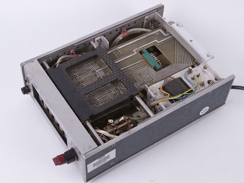
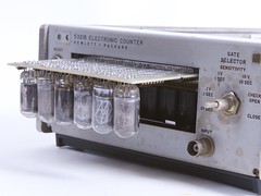
Under the top cover, you can see the main circuit board, which contains the display logic and the tubes themselves, socketed.
 |
 |
 |
 |
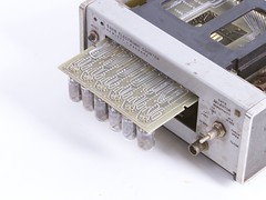
The main board is anchored in place with a couple of slot-tabs, and you essentially need to bend the board over a couple of tabs in order to slide it out. The nixie tubes hang upside down from the board, and have numbers that might seem upside down if you didn't know this.
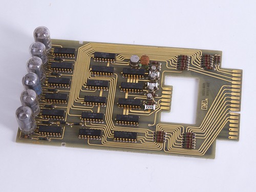
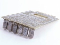
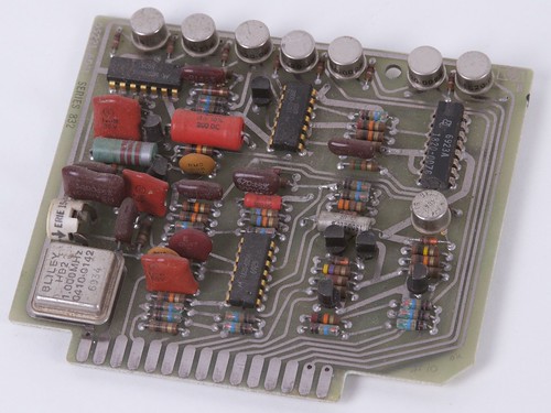
The board itself is something of a masterwork. The traces are thick and gold plated. It's soldered on the back side only, apparently by a dip-solder process. The chips are all now-generic types, but under HP part numbers ('1820-0093...') and the protruding letters 'hp' are molded right into the cases of each package. (You can see this photo in monstrous resolution here, if you're so inclined.)
There are three rows of chips on the board. The ones furthest from the tubes are cascading decade counter chips, the middle row are buffer chips, and those closest to the tubes are the Nixie driver chips.
For a little background, consider how this board works as part of the overall counter instrument. The input clock signal to the board goes to one decade counter chip (the rightmost). When that chip overflows, i.e., counts up from 9 to 0, it also outputs a 'carry' signal to the next chip, which then counts at 1/10 the rate, and so on. By doing this, the decade counter chips, together, form a record of how many total input signals have been received since the instrument started counting. After the instrument counts the input signal for a set period of time (the 'gate' time), the values from those chips are loaded into the buffer chips, and the decade counters are reset to zero. The buffer chips output their stored values continuously to the Nixie driver chips, so that it can display the last count.
You'll notice that the back row appears to only have five decade counter chips on it. It actually has six, where the sixth is the large metal can. This is the decade counter chip for the rightmost decimal place on the counter, which has to count ten times as fast as its neighbor. For this counter chip alone, HP used a higher performance version (in the metal can) that can count faster than the others.
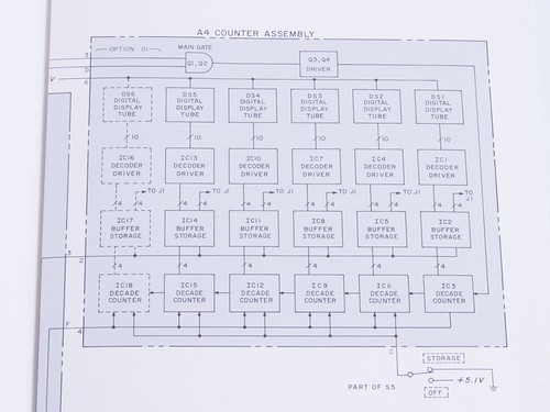
And, here's the block diagram from the manual showing how those pieces work together. The busses between the decade counter, buffer, and Nixie driver chips are 4-bit wide, binary coded decimal.
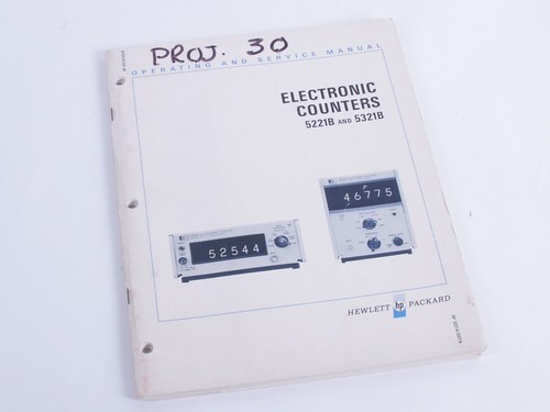
(They don't make 'em like they used to, referring to the manuals of course.)
Now, to begin modifications. The basic fact that we need to overcome is that this is a decade counter-- each digit rolls over from 9 to 0, while we want a digital clock to roll over from 59 to 0, 59 to 0, and 12 to 1.
Operating the clock, we count at 1 second intervals, triggered on internally-generated 1 s gate signal, counted down from the internal timebase. We could in 'open' gate mode, where we do not reset the count every time that there is a new gate. (In other words, we're using this clock like a pulse counter rather than like a frequency counter.)
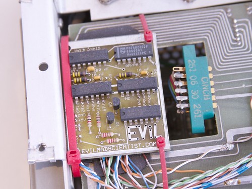
To that end, we cut traces on the circuit board, and route signals to our own circuit board, strapped into the chassis with cable ties and insulated by foam rubber. The board has four 7402 'Quad Input NOR Gate' chips onboard, along with a 74107 'Dual J-K Flip Flop' and a couple of transistors.
For the two rightmost digits, the seconds on our clock, we look at the binary-coded decimal output of the counter chips, and detect when the displayed characters are '60.' That's actually simpler than it sounds, since we only need to detect the '6,' and that is represented by the first low on two specific pins of the decade counter BCD output.
Once we've detected the '6,' we reset that chip to zero and send the carry signal to the next chip over, the first digit of the minutes on our clock. The reset input for the chip takes a positive going pulse of 3 microseconds, driven through an npn transistor. We generate that pulse with a simple one-shot, built with two NOR gates-- a classic example of what is known as MML, 'Mickey Mouse Logic.'
For detecting 60 minutes, we do the exact same thing, carrying an output to increment the hours every 60 minutes.
It is somewhat more complex to display the hours. The 'native' counting order of the decade counters is 0,1,2,3,4,5,6,7,8,9,10,11,12,13 (...). However, we don't want to display zero; we want to wrap around and display the count as 1,2,3,4,5,6,7,8,9,10,11,12,1,2 (...).
We actually did this by rewiring the ten outputs of the Nixie decoder driver, between that chip and the tube (for the 1-hour place), so that the tube is lit up as '1' when its input is BCD0, and so forth. We then need to detect BCD9 (again, two specific lows detected with a NOR gate), to generate the carry signal to the ten-hours. After the chip outputs BCD9 (displaying '0') it increments to BCD0, where it displays '1'-- resetting itself.
For rolling over from 12:59 to 1:00, we want to detect a reading of '13' on the display. This requires actually looking for an 'internal' reading of BCD1,BCD2. This is easily detected with a fourth NOR gate, reading the low signals that indicate both '1' and '2.' The output of this gate resets the two hour digit counters back to zero-- which is displayed as 01. Zero-blanking, to just display '1:00' canbe accomplished by simply disconnecting the trace that would otherwise light up the 0 on the ten-hours digit.
One might alternately wish to build this into a 24-hour clock. That would be equally straightforward, by detecting BCD '2,3' as the reset condition.
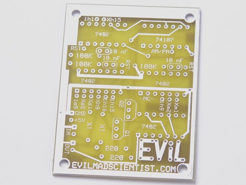
Here's the circuit board alone; nothing special about it, with one possible non-technical exception. As we said, making these clocks has been a longstanding project for us. And, this right here is the very first circuit board to bear the Evil Mad Scientist badge; it dates back to 2003.
There's one other feature on the circuit board that we haven't discussed yet, which is that it can recognize and indicate AM and PM times. Remembering which state we're in requires a single bit of memory, for which we use that flip-flop chip. We detect the switch from AM to PM times (and vice versa) when the clock reads '12', meaning that we read the BCD '1,1' on the two leading digits, using one NOR gate.
The state is stored by the flip flop, and indicated using the 'Gate' neon indicator, that you can see in the upper right corner of the front panel-- the neon light is on for PM times. You can't drive the neon bulb directly from the flip-flop chip, so we actually hijack the circuitry that originally drove that indicator. The 'Gate' indicator signal comes from the timebase board, not the main counting/display board that we've talked about so far, so the output from our flip-flop goes to that board, where we cut a trace and use our AM/PM signal instead.
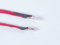
Speaking of neon bulbs, there are two additional neon bulbs that we have added to the clock, which are the small 'decimal point' lights that you can see in the photo above, separating hours, minutes, and seconds.
 |
 |
The separators are plain miniature neon bulbs, and each has a series resistor hidden in the heat shrink tubing. They are wired in parallel, across line voltage (live to ground) so that they're always on when the clock is switched on.
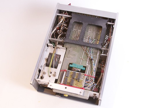
This is the timebase board. There are similar frequency counters that use the line frequency as their reference, but this board is based around a 1 MHz quartz crystal. The seven cans at the back of the board are high frequency decade counter chips like the one found on the main board. They count down the timebase, giving 100 kHz, 10 kHz, 1 kHz, 100 Hz, 10 Hz, 1 Hz, and 0.1 Hz output signals that can be used for gating and frequency counting.
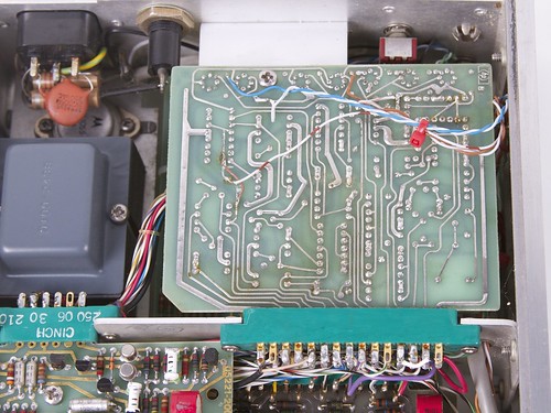
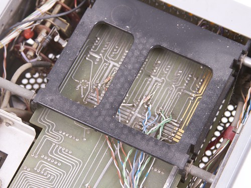
Here's what the underside of one of those boards looks like, as installed in the counter with our modifications. The circuit board color is slightly different in this particular unit, but it's the same otherwise.
The striped wire going to the middle left of the board is carrying our AM/PM signal to the logic that drives the front-panel neon bulb. The other wires are where we tap off the timing signals for our own purposes. The most important of these signals are the 1 Hz and 1 kHz signals. The 1 Hz signal is re-routed as the input to the counter-- the signal that we actually count to give the time -- and the 1 kHz signal is an auxiliary clock that we use as part of the time setting process.
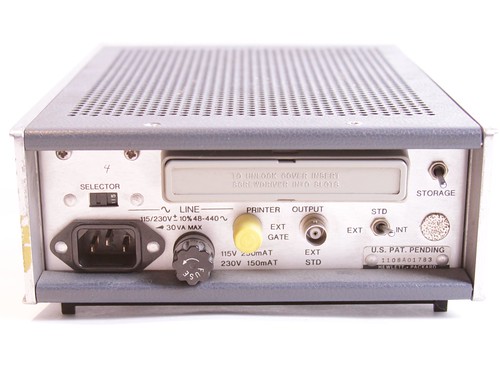
We repurposed the rear-panel 'Storage' switch as another part of the system for setting the time.When 'storage' is off, the 1 Hz timing signal goes into the input. When 'storage' is on, the 1 Hz signal is disconnected, but the pressing the front-panel 'Reset' button advances the clock at 1 kHz, using the other signal that we picked off of the timebase board.
So, to set the time precisely, you can flip up the 'storage' switch, press 'Reset' until the time is within a minute of the actual time, and then flip down the 'storage' switch (to start running in real time again) when the clock displays the right time.
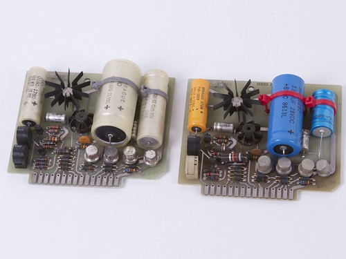
These counters are relatively old, and for the most part work surprisingly well considering their age. One place that failures can commonly crop up is on the power supply board. The one on the right had a resistor burn out at some point, which we replaced, and we also decided to replace its large electrolytic capacitors with ones 15-20 years younger.
And that's about the size of it.
These certainly aren't the only old frequency counters that can be made into clocks, but the particular blend of technology here-- easy to use TTL chips and Nixie tubes --is a friendly one for hacking, with potentially neat results. If you'd like to get into it, just grab a few of these old guys and poke and prod and see how they work. Get the manuals if you can, and keep in mind that there's plenty of line voltage, or even high voltage for the Nixie tubes, coursing through the veins of these boxes."