
An ever-present challenge in electronic circuit design is selecting suitable components that not only perform their intended task but also will survive under foreseeable operating conditions. A big part of that process is making sure that your components will stay within their safe operating limits in terms of current, voltage, and power. Of those three, the "power" portion is often the most difficult (for both newcomers and experts) because the safe operating area can depend so strongly on the particulars of the situation.
In what follows, we'll introduce some of the basic concepts of power dissipation in electronic components, with an eye towards understanding how to select components for simple circuits with power limitations in mind.
— STARTING SIMPLE —
Let's begin with one of the simplest circuits imaginable: A battery hooked up to a single resistor:
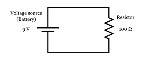
Here, we have a single 9 V battery, and a single 100 Ω (100 Ohm) resistor, hooked up with wires to form a complete circuit.
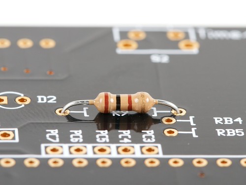
Easy enough, right? But now a question: If you want to actually build this circuit, how "big" of a 100 Ω resistor do you need to use to make sure that it doesn't overheat? That is to say, can we just use a "regular" ¼ W resistor, like the one shown below, or do we need to go bigger?
To find out, we need to be able to calculate the amount of power that the resistor will dissipate. Here's the general rule for calculating power dissipation:
If a current I flows through through a given element in your circuit, losing voltage V in the process, then the power dissipated by that circuit element is the product of that current and voltage: P = I × V.
How can current times voltage end up giving us a "power" measurement?
To understand this, we need to remember what current and voltage physically represent.
Electric current is the rate of flow of electric charge through the circuit, normally expressed in amperes, where 1 ampere = 1 coulomb per second. (The coulomb is the SI unit of electric charge.)
Voltage, or more formally, electric potential, is the potential energy per unit of electric charge --across the circuit element in question. In most cases, you can think of this as the the amount of energy that is "used up" in the element, per unit of charge that passes through. Electric potential is normally measured in volts, where 1 volt = 1 joule per coulomb. (The joule is the SI unit of energy.)
So, if we take a current times a voltage, that gives us the amount of energy that is "used up" in the element, per unit of charge, times the number of those units of charge passing through the element per second:
1 ampere × 1 volt =
1 ( coulomb / second ) × 1 ( joule / coulomb ) =1 joule / second
The resulting quantity is in units of one joule per second: a rate of flow of energy, better known as power. The SI unit of power is the watt, where 1 watt = 1 joule per second.
Finally then, we have
1 ampere × 1 volt = 1 watt
Back to our circuit! To use the power rule (P = I × V), we need to know both the current through the resistor, and the voltage across the resistor.
First, we use Ohm's law ( V = I × R ), to find the current through the resistor.
• The voltage across the resistor is V = 9 V.
• The resistance of the resistor is R = 100 Ω.
Therefore, the current through the resistor is:
Then, we can use the power rule ( P = I × V ), to find the power dissipated by the resistor.
• The current through the resistor is I = 90 mA.
• The voltage across the resistor is V = 9 V.
Therefore, the power dissipated in the resistor is:
So can you go ahead and use that 1/4 W resistor?
No, because it would likely fail from overheating. The 100 Ω resistor in this circuit needs to be rated for at least 0.81 W. Generally, one picks the next larger available size, 1 W in this case.
A 1 W resistor typically comes in a much larger physical package, like the one shown here:
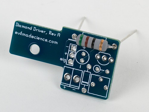
(A 1 W, 51 Ω resistor, for size comparison.)
Because a 1 W resistor is much larger physically, it should be able to handle dissipating a higher amount of power, with its higher surface area and wider leads. (It may still get very hot to the touch, but it should not get hot enough that it fails.)
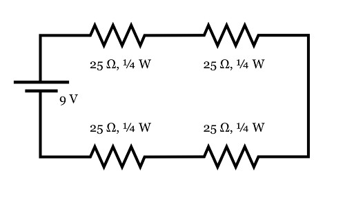
Here's an alternate arrangement that works with four 25 Ω resistors in series (which still adds up to 100 Ω). In this case, the current through each resistor is still 90 mA. But, as there is only one quarter as much voltage across each resistor, there is only one quarter as much power dissipated in each resistor. For this arrangement, one only needs the four resistors to be rated for 1/4 W.
— ON BEYOND RESISTORS —
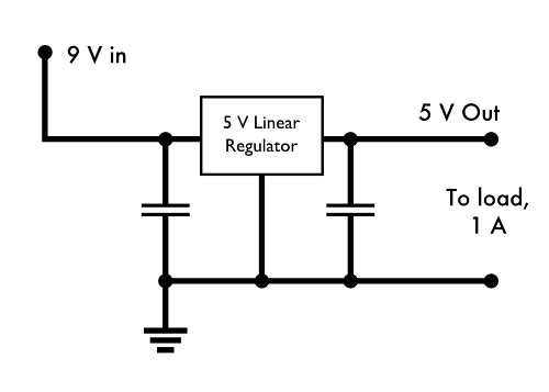
For our next example, let's consider the following situation: Suppose that you have a circuit that takes input from a 9 V power supply, and has an onboard linear regulator to step the voltage down to 5 V, where everything actually runs. Your load, on the 5 V end, could be as high as 1 A.
What does the power look like in this situation?
The regulator essentially acts like a big variable resistor, that adjusts its resistance as needed to maintain a consistent 5 V output. When the output load is a full 1 A, the output power delivered by the regulator is 5 V × 1 A = 5 W, and the power input to the circuit by the 9 V power supply is 9 W. The voltage dropped across the regulator is 4 V, and at 1 A, that means that 4 W is dissipated by the linear regulator-- also the difference between the power input and the power output.
In each part of this circuit, the power relationship is given by P = I × V. Two parts-- the regulator and the load -- are places where power is dissipated, while across the power supply, P = I × V describes the power input to the system-- the voltage increases as the current travels across the power supply.
Additionally, it is worth noting that we have not said what kind of load is pulling that 1 A. Just because power is being consumed does not necessarily mean that it is being converted into a steady flow of heat energy-- it may be powering a motor, or powering a set of battery chargers.
While this is a very common setup for electronics, it's worth pointing out that this is also an incredibly inefficient arrangement: 4/9 of the input power is simply burned off as heat, even when operated at lower currents.
— WHEN THERE ISN'T A SIMPLE "POWER" SPECIFICATION —
Next, a slightly more challenging part: making sure that your regulator can handle the power. While resistors are clearly labeled with their power capacity, linear regulators are not always. In our regulator example above, let's further suppose that we're using a L7805ABV regulator from ST (datasheet here).
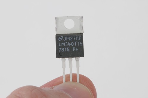 (Photo: A typical TO-220 case, the type typically used for medium-power linear regulators)
The L7805ABV is a 5 V linear regulator in a TO-220 package (similar to the one shown above), that is rated for 1.5 A output current and up to 35 V input voltage.
Naively, you might guess that you can hook this right up to 35 V input, and expect to get 1.5 A of output, meaning that the regulator would be radiating 30 V * 1.5 A = 45 W of power. But this is a tiny plastic package-- it actually can't handle that much power. If you look in the datasheet under the "Absolute maximum ratings" section, to try and find how much power it can handle, all that it says is "Internally limited"-- which is anything but clear on its own.
It does turn out that there is an actual power rating, but it's usually somewhat "hidden" within the datasheet. You can figure it out by looking at a couple of related specifications:
• TOP, Operating junction temperature range: -40 to 125 °C
• RthJA, Thermal resistance junction-ambient: 50 °C/W
• RthJC, Thermal resistance junction-case: 5 °C/W
The Operating junction temperature range, TOP, specifies how hot the "junction"-- the active part of the regulator integrated circuit --can be allowed to get before it goes into thermal shutdown. (The thermal shutdown is the internal limit that makes the regulator power "Internally limited".) For us, that's a maximum of 125 °C.
The thermal resistance junction-ambient RthJA (Often written as ΘJA), tells us how hot the junction gets when (1) the regulator is dissipating a given amount of power and (2) the regulator is sitting in open air, at a given ambient temperature. Suppose that we need to design our regulator to only work under modest commercial conditions, that will not exceed 60 °C. If we need to keep the junction temperature under 125 °C, then the maximum temperature rise that we can allow is 65°C. If we have RthJA of 50 °C/W, then the maximum power dissipation that we can allow is 65/50 = 1.3 W, if we are to prevent the regulator from going into thermal shutdown. That's well below the 4 W that we would expect with a 1 A load current. In fact, we can only tolerate 1.3 W / 4 V = 325 mA of average output current without sending the regulator into thermal shutdown.
This, however, is for the case of the TO-220 radiating to ambient air-- almost a worst-case situation. If we can add a heat sink or otherwise cool the regulator, we can do much better.
The opposite end of the spectrum is given by the other thermal specification: the thermal resistance junction-case, RthJC. This specifies how much temperature difference you can expect between the junction and the outside of the TO-220 package: only 5 °C/W. This is the relevant number if you can quickly remove heat from the package, for example if you have a very good heat sink hooked up to the outside of the TO-220 package. With a big heat sink and perfect coupling to that heat sink, at 4 W, the junction temperature would rise only 20 °C above the temperature of your heat sink. This represents the absolute minimum heating that you can expect under ideal conditions.
Depending on the engineering requirements, you can start from this point to build a full power budget, to account for the thermal conductivity of every element of your system, from the regulator itself, to the thermal interface pad between it and the heat sink, to the thermal coupling of the heat sink to the ambient air. You can then verify the couplings and relative temperatures of each component with a spot-reading non-contact infrared thermometer. But often, it's a better choice to re-evaluate the situation and see if there's a better way to go about this.
For the present situation, one might consider moving to a surface mount regulator that offers better power handling capability (by using the circuit board as a heat sink) or it may be worth looking into adding a power resistor (or zener diode) before the regulator to drop some most of the voltage outside the regulator package, easing the load on it. Or better yet, seeing if there's a way to build your circuit without the lossy linear regulator stage.
— AFTERWORD —
We have covered the basics of understanding power dissipation in a few simple, dc circuits.
The principles that we have gone over are quite general, and can be used to help understand power consumption in most types of passive elements and even most types of integrated circuits. There are real limitations, however, and one could spend a lifetime learning the nuances of power consumption, particularly at lower currents or high frequencies where small losses that we have neglected become important.
In ac circuits, many things behave very differently, but the power rule still holds in most circumstances: P(t) = I(t) × V(t) for time-varying current and voltage. And, not all regulators are all that lossy: Switching power supplies can convert (for example) 9 V dc to 5 V dc with 90% or higher efficiency-- meaning that with good design, it may only take about 0.6 A at 9 V to produce 5 V at 1 A. But that's a story for another time.